


SKYLOOP 40 · Horizontal Full-Wave Loop Antenna
A 141 ft horizontal full-wave loop for no-tuner operation on 40 and 20 meters, with tuner-supported coverage on 17, 15, 12, and 10 meters.
Full-size loop performance in a practical 40-meter footprint
Build a quieter, stronger fixed or semi-permanent HF station
The CHA SKYLOOP 40 gives operators the receive-noise and broad radiation advantages of a horizontal full-wave loop without requiring the 286 ft footprint of the SKYLOOP 2.0. Its 141 ft loop is designed for 40 and 20 meter operation without an antenna tuner under a suitable installation.
With a compatible antenna tuner, the same installed loop also supports 17, 15, 12, and 10 meters. Four relatively short sides make it practical for small lots, HOA-conscious installations, base camps, emergency communications, and shortwave listening where a long straight wire is difficult to place.
Height and geometry remain operating tools. A higher, well-shaped loop supports broader regional and long-distance work; a lower horizontal installation strengthens the high-angle radiation useful for Near-Vertical Incidence Skywave communication.
Quick product reference
Key Specifications
- Product type
- Horizontal full-wave wire loop
- No-tuner bands
- 7.0-7.3 MHz (40 m) and 14.0-14.35 MHz (20 m)
- With a tuner
- 18.068-18.168 MHz (17 m), 21.0-21.45 MHz (15 m), 24.89-24.99 MHz (12 m), and 28.0-29.0 MHz (10 m)
- Power
- 500 W SSB, 250 W CW, 100 W digital modes
- Matching network
- Integral broadband 2.5:1 transformer
- RF connection
- SO-239 UHF connector
- Loop length
- 141 ft total, 16-gauge wire
- Nominal geometry
- Approximately 35 1/4 ft per side when installed as a square; published diagrams round the layout to roughly 36 ft
- 2:1 bandwidth
- 350 kHz minimum
- SWR objective
- Less than 2.0:1 at resonance; verify the completed installation before transmitting
- Lowest optimal height
- Approximately 30 ft; lower installations remain usable with different efficiency and radiation characteristics
- Weight
- 2 lb 8 oz
- Color
- Gray, black, and green
- Primary operating roles
- Home/base station, small lot and HOA, base camp, EMCOMM/NVIS, and shortwave listening
Operator decision support
Plan the complete installation
The loop is tolerant of an imperfect site, but total wire length, safe support points, feed-line routing, and final analyzer verification still control the result.
- Best for
Operators who can provide four safe support points and want a low-noise, high-performance 40/20 m loop for a home, restricted property, base camp, or emergency communications site.
- What’s included
- CHA SKYLOOP 40 matching transformer unit
- 141 ft 16-gauge loop-wire assembly with isolation rings, carabiners, spade-lug connections, and end-insulator tuning strip
- Line winder
- Field-tuning spade-lug and heat-shrink supplies referenced by the manual
- What else you need
- Four safe support points using suitable trees, pole masts, fence posts, or building attachment points
- Paracord or equivalent support line
- 50-ohm coaxial feed line with the correct PL-259 connection
- Antenna analyzer or SWR meter for installation verification
- A compatible antenna tuner for 17, 15, 12, and 10 meters
- Weatherproofing for an exposed feed-line connection
- Documented support path
The manual specifically recommends the CHA PORTA-MAST as an available accessory. Trees, fence posts, building eaves, and suitable pole masts are also illustrated or named. Validate every support, attachment, line, and load as one mechanical system.
- Limitations
- The total loop length remains 141 ft except for careful resonance trimming.
- Changing height, shape, ground conditions, or nearby objects can move resonance.
- A shared connector or convenient physical fit does not establish support, RF, or complete-system compatibility.
- Never install any antenna or support near power lines.
Seven-band engineering model
Broad regional coverage. Concentrated upper-band DX performance.
The supplied EZNEC model shows the SKYLOOP 40 changing operating character as frequency increases. At 40 meters, the pattern is almost omnidirectional with very strong high-angle radiation. From 17 through 10 meters, the loop develops increasingly concentrated lower-angle lobes, with modeled maximum gain reaching 11.4 dBi on 10 meters in favored directions.
| Band | Frequency | Modeled maximum gain | Pattern character | Operating note |
|---|---|---|---|---|
| 40 m | 7.0 MHz | 6.7 dBi | Broad / very high angle | No tuner after installation verification |
| 30 m | 10.1 MHz | 6.0 dBi | Broad / high angle | Engineering characterization only; not a documented transmit-band claim |
| 20 m | 14.0 MHz | 6.4 dBi | Broad azimuth / medium-angle lobes | No tuner after installation verification |
| 17 m | 18.1 MHz | 9.4 dBi | Directional / lower angle | Suitable tuner required |
| 15 m | 21.0 MHz | 10.9 dBi | Multi-lobed / lower angle | Suitable tuner required |
| 12 m | 24.9 MHz | 10.8 dBi | Four principal lobes | Suitable tuner required |
| 10 m | 28.0 MHz | 11.4 dBi | Narrow principal lobes | Suitable tuner required |
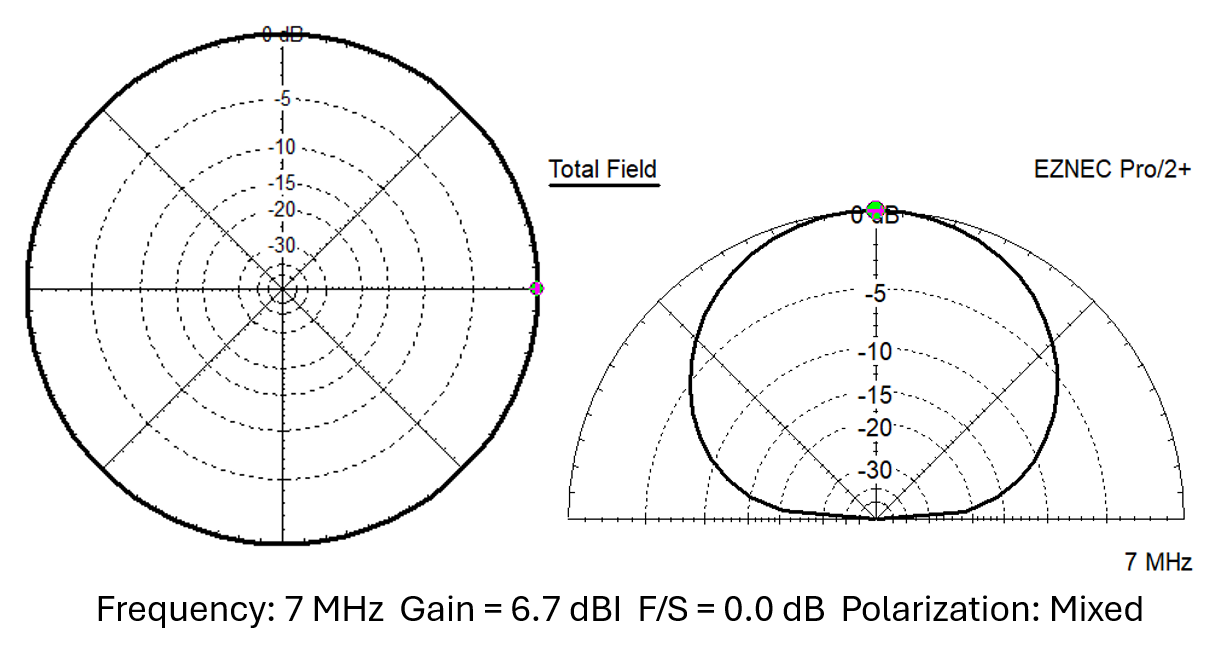
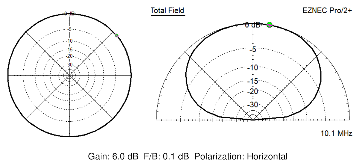
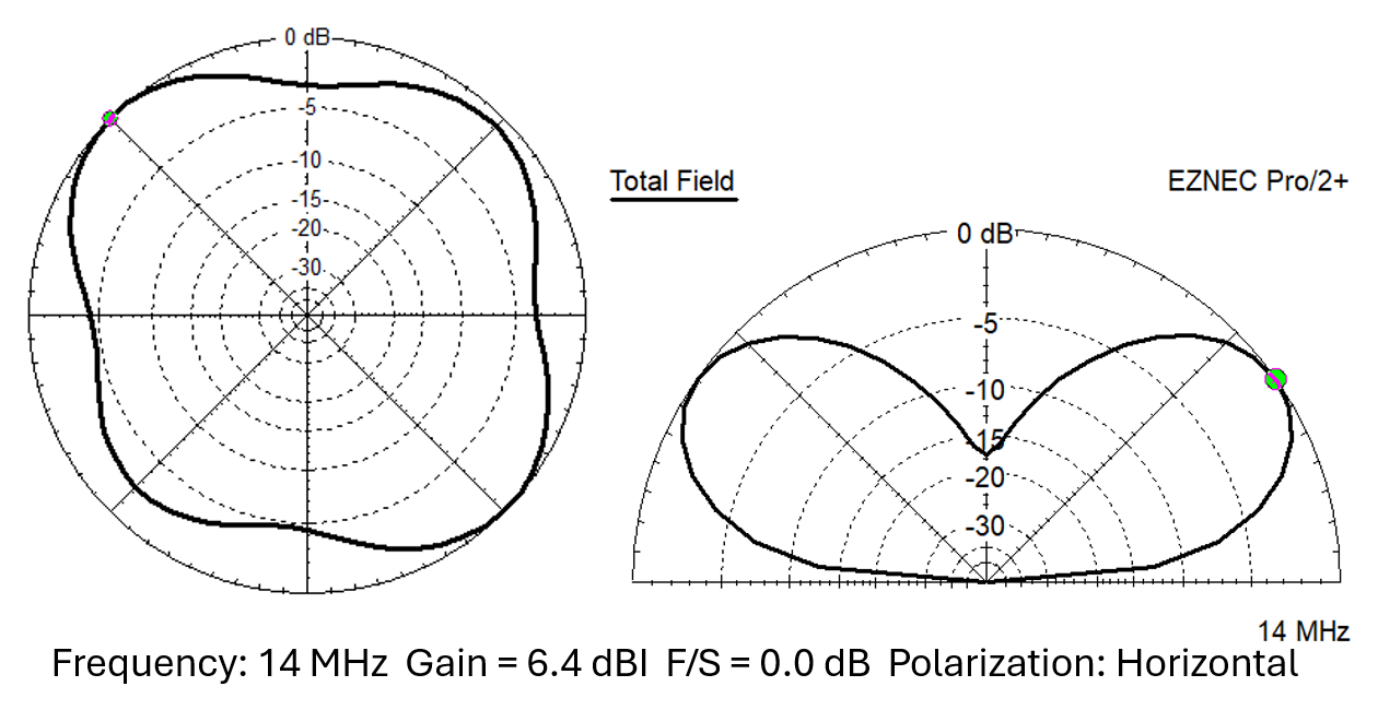
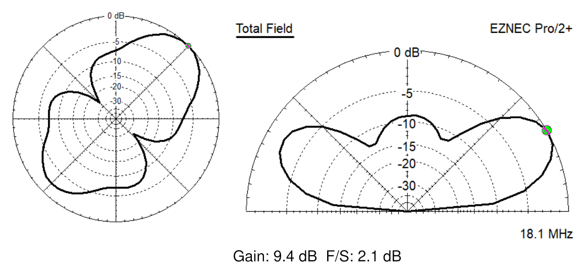
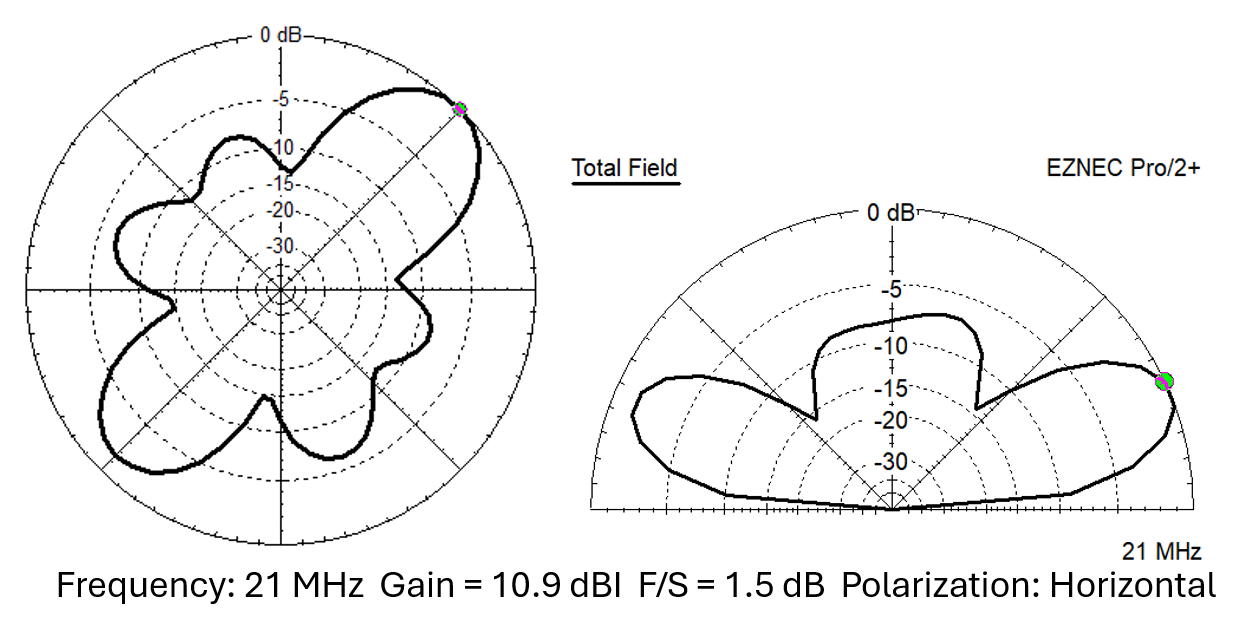
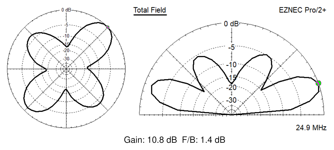
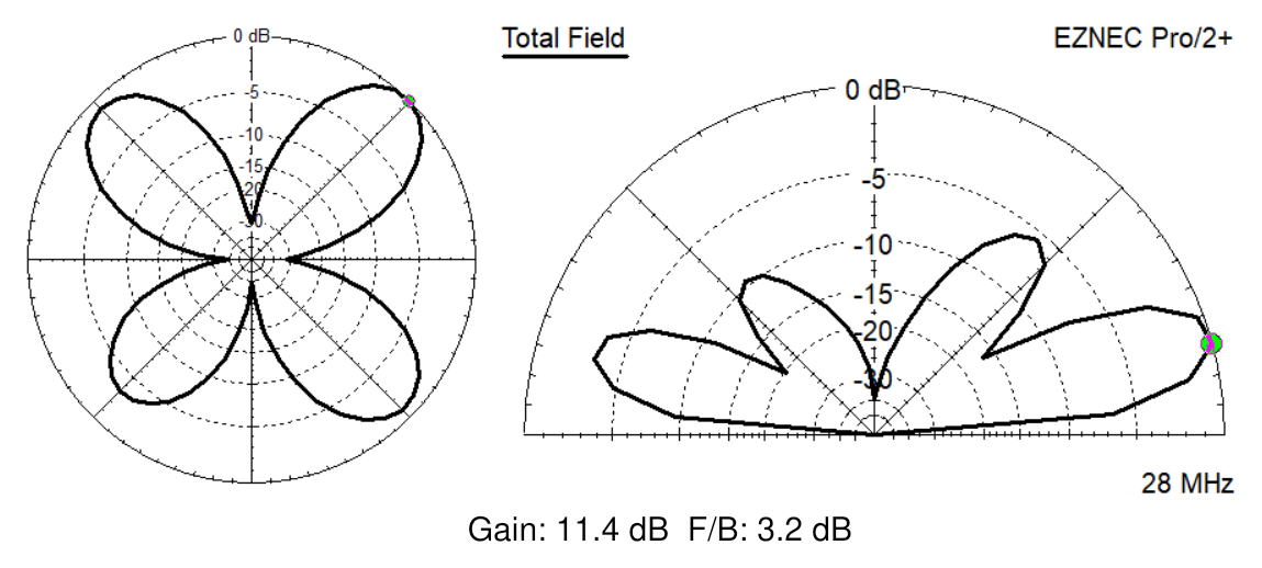
Orientation matters on the upper bands. Record the compass heading of each loop side and confirm favored directions with on-air reports, beacon data, or controlled measurements at the actual site. A modeled null is a relative weakness, not a guaranteed absence of communication.
What an operator can do
- Operate on 40 and 20 meters without a tuner after verifying the installed SWR.
- Use a suitable tuner for documented operation on 17, 15, 12, and 10 meters.
- Shape the 141 ft loop around a real property when a perfect square and four equal-height supports are not available.
- Install the loop higher for general regional and DX work or lower for stronger NVIS-oriented coverage, while observing RF-exposure and support safety.
- Use the antenna as a low-noise shortwave-listening loop across a broader receive range.
Installation sequence
- Plan four safe corners and the feedpoint location. Start near 35 1/4 ft per side, then adapt individual side lengths to the site while preserving the 141 ft total loop length.
- Support the matching-transformer eyebolt with a bowline and paracord. Attach both loop-wire carabiners for strain relief before connecting both spade lugs to the wing-nut terminals.
- Connect the coaxial feed line to the SO-239 and weather-seal the outdoor connection.
- Raise the matching transformer, then raise the remaining corners from the floating isolation rings.
- Adjust shape and tension without loading the electrical terminals mechanically.
- Measure the completed antenna at low power before transmitting.
Field tuning guardrails
- If SWR is 2.0:1 or less at both 7.000 and 7.300 MHz, the manual recommends leaving the wire length unchanged.
- If SWR is higher at 7.300 MHz and lower at 7.000 MHz, the loop is electrically long for the desired part of the band.
- Trim only through the end-insulator strip procedure. Leave approximately 7 in of wire beyond the strip for strain relief and transformer connection.
- The guide’s field example indicates approximately 60 kHz upward resonance shift per foot removed. Treat that only as a careful starting estimate because each site changes the result.
- Trim in small steps and remeasure the complete installed loop after every change. Removed wire cannot be restored easily.
Safety, inspection, and weather protection
- Keep the antenna, supports, ladders, ropes, and feed line away from every power line and utility wire.
- Maintain required RF-exposure separation, especially above 10 W or above 14 MHz, and keep the antenna away from RF-sensitive medical devices.
- Inspect the loop wire, isolation rings, carabiners, spade lugs, wing nuts, enclosure, SO-239, coax, support cord, and anchors before raising the system.
- Provide drip loops and weatherproof outdoor coax connections. Disconnect and protect station equipment when the antenna is not safely in service.
- The ground terminal does not replace a complete code-compliant lightning and station-grounding plan.

