Step 01
Identify the exact radio
Manufacturer, nomenclature and variantSimilar-looking radio families can use different frequency coverage, connectors, accessories, control logic and approved operating limits.

Chameleon Military HF Capability Center
A practical, public-source starting point for military and government teams choosing portable HF systems, regional NVIS, beyond-line-of-sight paths, directional UHF, operator resources, and the right commercial purchasing route.
Decision boundary: this center supports requirement definition and product evaluation. It does not replace receiving-unit engineering, spectrum management, COMSEC, safety, airworthiness, platform integration or command approval.
Military capability overview
This page brings Chameleon Antenna’s military field systems, configuration guidance, operator resources, and engineering evidence into one practical decision path.
Use it to turn a broad mission need into a short list, compare deployment burden, understand the complete radio-to-antenna chain, open setup documentation, and review governed 2D and interactive 3D NEC patterns when engineering detail is useful.
Start the Mission Configuration GuideNEW HERE? START WITH THE GUIDED TOUR
In about seven minutes, see how to define an unclassified requirement, compare field-system families, qualify the complete radio chain, read NEC evidence, plan sustainment, and choose the right commercial purchasing route.
Continue to the Mission Configuration GuideMission Configuration Guide
You do not need to know antenna theory or arrive with a shopping list. Answer the operational questions you can answer. The guide will identify reasonable Chameleon families for discussion and flag what still needs to be confirmed.
Starting point—not an automatic recommendation
Fast system comparison
This table compares roles and deployment burden. Open the detailed family record before treating any product as a candidate for a specific radio or mission.
On a phone, each system is presented as a readable comparison card.
| System | Spectrum / role | Mobility | Supports | Primary strength |
|---|---|---|---|---|
| TACYAGI-70 | UHF directional LOS · 400–470 MHz | Dismounted / transportable | Handheld or suitable mount | Direction finding and focused line-of-sight work |
| MPAS 2.0 | HF · vertical and wire | Portable | None for vertical; support for wire | Broadest field configuration family |
| MPAS Lite | HF · vertical and wire | Lightweight portable | None for vertical; support for wire | Approximately 4 lb complete field package |
| TDL | HF · loop, vertical, and dipole | Portable | Configuration-dependent | Four documented geometries in one kit |
| LEFS 8010 | HF · supported wire | Lightweight portable | One or two | Low carriage burden with 80 m option |
| NVIS family | HF · regional / NVIS | Deliberate portable | Center support or overhead point | Purpose-oriented regional geometry |
| TD 2.0 + HPD | HF · adaptable wire | Portable / deliberate | Configuration-dependent | Baseline kit with longer-wire expansion |
| EMCOMM III Portable | HF · contingency wire | Portable | One or two | Compact alternate wire path |
| EMCOMM III Base | HF · deliberate wire | Fixed / transportable | One or more | Long radiator for deliberate low-band work |
| SKYLOOP 40 | HF · compact loop | Fixed / semi-fixed | Four | Smaller deliberate loop footprint |
| SKYLOOP 2.0 | HF · full-size loop | Fixed / semi-fixed | Four | Large-aperture multiband site system |
| PORTA-MAST | Mechanical support subsystem | Fixed / stationary vehicle | Documented mount | Repeatable portable antenna support |
Controlled field-system families
These are planning candidates—not military endorsements or automatic radio matches. Every operational build still requires an exact bill of material, authorized radio chain, field geometry, safety review, verification method and receiving-unit approval.
Operational context: HF can support command-post and beyond-line-of-sight continuity when terrain, distance, damaged infrastructure, congestion, or displacement makes shorter-range networks insufficient.
What to evaluate: Compare deliberate loop and wire systems for sustained sites, dedicated NVIS geometry for regional paths, and controlled portable verticals for constrained or rapidly changing positions. Preserve antenna separation, feed-line routing, grounding, lightning protection, electromagnetic compatibility, frequency planning, and the complete PACE role.
Approval boundary: A planning candidate is not Army adoption or authority to connect to a tactical radio. The receiving organization controls radio interfaces, spectrum, COMSEC, safety, siting, and configuration approval.
Read the U.S. Army HF and BLOS sourceOperational context: Expeditionary communications planning balances range, displacement time, transport burden, site footprint, operator workload, and the ability to rebuild a known configuration after movement.
What to evaluate: Compare portable modular HF systems, controlled field-wire configurations, and dedicated regional NVIS paths by setup time, support requirements, return-current control, frequency agility, and sustainment burden. A directional UHF antenna belongs to a separate line-of-sight planning path; the TACYAGI-70 covers 400–470 MHz and does not cover VHF.
Approval boundary: Civilian documentation remains a training reference when a ruggedized operational version is required. Unit engineering, spectrum, COMSEC, safety, and equipment-authority decisions remain controlling.
Read the Marine Corps HF planning sourceOperational context: Shore and contingency-construction teams may require HF continuity between dispersed land sites when terrestrial or satellite services are limited, unavailable, or reserved for other traffic.
What to evaluate: Deliberate loops and base wires suit sites with supports and space; portable systems support temporary or alternate positions. Record salt exposure, corrosion control, wind, soil, grounding, lightning protection, cable routing, antenna-farm separation, and the exact shore-site mission.
Approval boundary: Shore suitability does not establish shipboard qualification, topside integration, emissions control, or Navy system approval.
Read the U.S. Navy HF continuity sourceOperational context: HF can contribute to resilient communications at dispersed or contingency locations and to partner training where long-distance paths must remain available outside a single infrastructure dependency.
What to evaluate: Compare transportable loops, field wires, NVIS systems, and portable verticals by path, setup time, footprint, support availability, frequency plan, trained crew, and repeatability. Include airfield and facility siting restrictions, grounding, lightning protection, and electromagnetic compatibility.
Approval boundary: No antenna selection here establishes airworthiness, flight-line authorization, frequency approval, cybersecurity, COMSEC, or integration with an Air Force radio system.
Read the U.S. Air Force HF training sourceOperational context: Terrestrial HF can be evaluated as one continuity layer for ground-support activities; it is not presented as a substitute for satellite command, tracking, telemetry, or protected mission networks.
What to evaluate: Focus on fixed or transportable ground-site configurations, alternate communications paths, antenna siting, interference control, spectrum coordination, facility grounding, cybersecurity boundaries, and trained operating procedures.
Approval boundary: A commercial HF antenna does not establish compatibility with space systems, protected networks, mission data, classified operations, or a Space Force technical baseline.
Read the Space Force terrestrial-continuity sourceOperational context: Remote shore stations, temporary response sites, and high-latitude evaluations can place unusual demands on communications range, weather tolerance, logistics, and local infrastructure.
What to evaluate: Compare portable and fixed HF paths by deployment speed, regional versus long-distance coverage, wind and ice exposure, corrosion, ground conditions, support security, generator or battery availability, and the need to reproduce the installation during a response.
Approval boundary: Shore or field evaluation does not establish cutter installation, marine environmental qualification, SAR-system certification, or authorization for a Coast Guard radio chain.
Read the U.S. Coast Guard evaluation sourceOperational context: Publicly described special-operations support and partner-capacity activities can require equipment familiarization, fixed support, headquarters continuity, and interoperability planning.
What to evaluate: Use the controlled product and pattern evidence for equipment-selection, support-site, and partner-headquarters decisions. Define the radio chain, waveform, spectrum, path, deployment signature, transport burden, sustainment, and receiving-organization approvals before selecting hardware.
Approval boundary: No infiltration, concealment, low-probability-of-intercept, signature-management, special-operations adoption, or mission-suitability claim is made.
Read the U.S. SOCOM public capability sourceOperational context: A partner headquarters needs more than a common connector. Interoperability depends on compatible standards, frequencies, waveforms, channel plans, security rules, equipment profiles, operating procedures, and national authorization.
What to evaluate: Begin with the NATO Interoperability Standards and Profiles record, then identify the participating nations, authorized radio systems, network role, HF path, interface standards, information-assurance boundary, training plan, spares, and configuration-control process. Evaluate the antenna only as one subsystem in that governed chain.
Approval boundary: A Chameleon antenna does not create NATO interoperability, establish NATO codification, satisfy a national cryptographic requirement, or replace host-nation and receiving-headquarters approval.
Read the NATO interoperability standards profileRetired scope boundary: service labels identified plausible planning environments only and never implied adoption or approval.
A compact directional UHF antenna for situations where bearing, front-to-back discrimination, or a focused line-of-sight path matters more than omnidirectional coverage. The controlled user guide specifies 400–470 MHz; this product is not presented as a VHF antenna. It belongs in a separate planning path from the HF systems on this page.
A 141-foot, four-support loop with a known near-square electrical footprint for command posts and alternate sites.
Model boundary: Seven product-specific EZNEC far-field cases supplied for the 141 ft loop remain valid source-governed evidence. The representative 20 m 3D view is a disclosed reconstruction from the supplied azimuth and elevation cuts—not a native rerun—because the original wire coordinates, segmentation, source, numerical ground constants, loss controls, and absolute reference azimuth were not supplied.
A 286-foot, four-support horizontal loop with a known near-square electrical footprint for headquarters, continuity sites and remote antenna farms.
The broadest portable configuration family in this center. Its documented vertical paths include CHA MIL WHIP 2.0 and CHA MIL EXT 2.0 radiator components above the governed MPAS feed system; they are configurations of CHA MPAS 2.0, not separate antenna-system families. Use the CHA MINI feed unit when its higher-power ICAS boundary matches the exact authorized radio chain.
A compact Tactical Delta Loop system that can be configured as an inverted delta loop, ground-mounted vertical, horizontal dipole for NVIS work, or V dipole. The selected geometry—not the product name alone—defines the pattern and operating boundary.
A lighter modular field system for vertical, end-fed inverted-V, sloping-wire, and horizontal NVIS configurations when carriage burden and rapid reconfiguration matter.
A lightweight end-fed half-wave system for sloper and horizontal NVIS deployments. The military page prioritizes the full 130 ft combined-wire configuration because it provides the documented 80 m path. The 63 ft standard radiator remains a separate, fully identified evidence case for the higher-band configuration.
A purpose-oriented regional-HF starting system when skip-zone coverage, repeatable geometry and deliberate frequency planning matter.
Start with TD 2.0. Add the HPD only when the selected documented geometry benefits from longer wire elements or counterpoises and the site can support them.
Evidence boundary: HPD is not a stand-alone antenna. The published average 2.6 dB improvement below 14 MHz is a controlled-model result for specified counterpoise arrangements—not guaranteed field gain. Never substitute HPD into an undocumented position.
A 130-foot wire system for headquarters, emergency operations, alternate sites and remote fixed positions where supports and setup time are available.
A compact 73-foot radiator and 25-foot counterpoise system for rapid wire deployments where the operator has a suitable support and a controlled radio chain.
A portable support option for compatible wire and lightweight antenna deployments. It may be installed on a vehicle with the documented CHA HITCH MOUNT or CHA WHEEL MOUNT, or on a suitable structure with the documented fixed-mount path. It is a mechanical subsystem—not a radiation model or a universal approval for every antenna.
Public mission-planning sources: U.S. Army HF and BLOS · U.S. Marine Corps HF planning · U.S. Navy HF continuity · U.S. Air Force HF training · U.S. Space Force terrestrial continuity · U.S. Coast Guard HF evaluation · U.S. SOCOM public capability scope · NATO interoperability standards profile. These sources establish mission context only; they do not approve a Chameleon configuration.
Complete radio-chain review
Start with the exact authorized radio and follow the transmit path to the antenna. Military Systems & Technical Support needs the chain below before confirming a configuration.
Step 01
Similar-looking radio families can use different frequency coverage, connectors, accessories, control logic and approved operating limits.
Step 02
Record every component between the radio and antenna. The lowest power, duty-cycle and environmental limit governs the complete chain.
Step 03
HF regional or BLOS work, VHF/UHF line-of-sight work and directional signal-location work require different antenna paths.
Step 04
A mechanical adapter establishes fit only. It does not prove matching, power handling, common-mode control, radiation performance or platform approval.
Configuration boundary: Chameleon can identify a commercial antenna starting point and the required accessories. The receiving organization remains responsible for radio authorization, spectrum, COMSEC, waveform, cybersecurity, platform integration, safety and final acceptance.
CHA MPAS 2.0 - MIL operator resources
The MPAS 2.0 - MIL supports documented vertical and wire configurations for an approved radio-and-coupler chain. These setup and familiarization resources help customers relate each arrangement to the intended path, available supports, site limits, and verification method.
Service boundary: Chameleon provides product documentation and technical support. Chameleon does not provide military instruction, field courses, or certified training.

Unit-led familiarization resource
A 46-page, service-neutral product-support package covering accountability, configuration selection, propagation, power, SWR, safety, deployment, verification, troubleshooting, recovery, and practical exercises. Units may use it for their own familiarization; it is not a Chameleon-delivered course.
Open briefing and field guideControlling product document
Use the current manual for exact kit contents, assembly, ratings, configuration diagrams, maintenance and safety.
Open official manual →Technical reference
Continue into setup, compatibility, deployment planning, troubleshooting, and power handling.
Open CKB handbook →Bounded field and instructional evidence
These accounts describe specific third-party evaluations and instructional use. Chameleon does not provide military training, and receiving organizations must validate the antenna with their radios, sites, frequencies, procedures and measurement methods.
Published operational evaluation
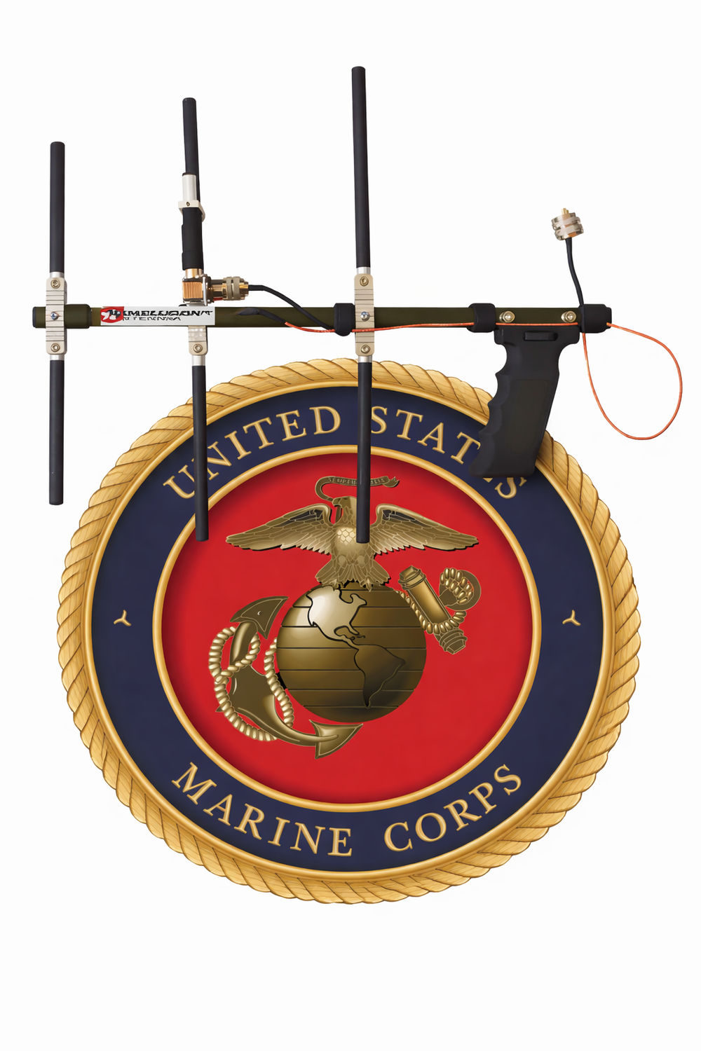
In the documented evaluation, the TACYAGI-70 was used as a directional alternative for UHF line-of-sight links. Reported outcomes apply to the tested conditions.
“I would buy this antenna for the squadron. Its price point is unbeatable and we don’t organically possess any directional antennas.”
Published instructional application
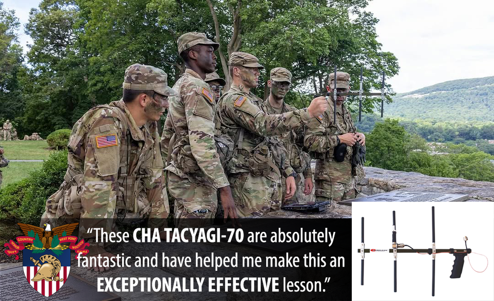
West Point instructors selected ten TACYAGI-70 antennas for a directional-antenna exercise involving beacon location, signal-strength observation and decoding.
“These Cha Yagis are absolutely fantastic and have helped me make this an exceptionally effective lesson.”
How to read the engineering evidence
NEC predicts the far-field behavior of one declared computer model. It is not a photograph of RF, a coverage map, a propagation forecast, or a guarantee of installed performance.
92-SECOND PATTERN BRIEFING
See how installation identity, elevation, azimuth, lobes, nulls and model limits turn a simulation into a better field-planning question without turning it into a performance promise.
Open the complete Pattern SchoolConfirm the product, frequency, geometry, height, ground, return system, solver, and evidence status. A changed setup is a different case.
Elevation is a side view: 0° is the horizon and 90° is overhead. Azimuth is a view from above at the stated elevation.
Bulges show favored modeled directions. Deep inward notches show reduced response and can matter more than a small gain advantage.
On a normalized plot, 0 dB is that plot’s strongest direction and −3 dB is about half its power density. It does not mean 0 dBi gain.
Rotate the volume to relate the 2D cuts. Its size is relative pattern level—not physical distance, range, visible RF, or field strength.
Ask whether the useful directions, elevation angles, polarization, and nulls fit the intended path. Then read the stated omissions and limits.
If you only need equipment-selection guidance, read “What the decision-maker should understand” in each record. If the pattern will influence engineering or emplacement, open the complete plain-language lesson first.
Open the complete NEC Pattern SchoolOptional engineering evidence · 2D + 3D
These representative accepted NEC-4 cases remain available after the mission, system, radio-chain, operator-resource, and field-evidence sections.
Open the expandable pattern evidenceMission-relevant pattern evidence
These accepted HF and UHF NEC-4 cases expose the direction and elevation tendencies most useful during early site and mission planning. They are selected examples—not sales promises. Open the full laboratory for every accepted frequency, geometry, assumption and evidence boundary.
This representative TACYAGI-70 case shows the directional behavior of the owner-measured three-element geometry at 430 MHz. It supports line-of-sight and direction-finding discussion; it is not a field-range guarantee or a substitute for the complete radio, feed-line, polarization, mounting, terrain and interference review.
Controlled model record
The reflector, driven element and director follow the controlled measured geometry. +X is the modeled forward direction, +Y is transverse to the boom, and +Z is up in the displayed reference. The source, gamma-match, feed line, handheld or mounted support, nearby conductors, operator coupling, terrain, polarization mismatch and complete RF-chain losses are not correlated.


Drag to rotate · scroll or pinch to zoom
Loading interactive pattern…
The forward lobe and rear rejection belong to this exact modeled orientation. Rotating the antenna changes the coverage bearing, and rotating its polarization changes compatibility with the other station. Actual usable range remains controlled by the complete link and operating environment.
Evidence state: simulation from owner-measured geometry · feed and installed environment uncorrelated · normalized pattern shape, not measured realized performance.
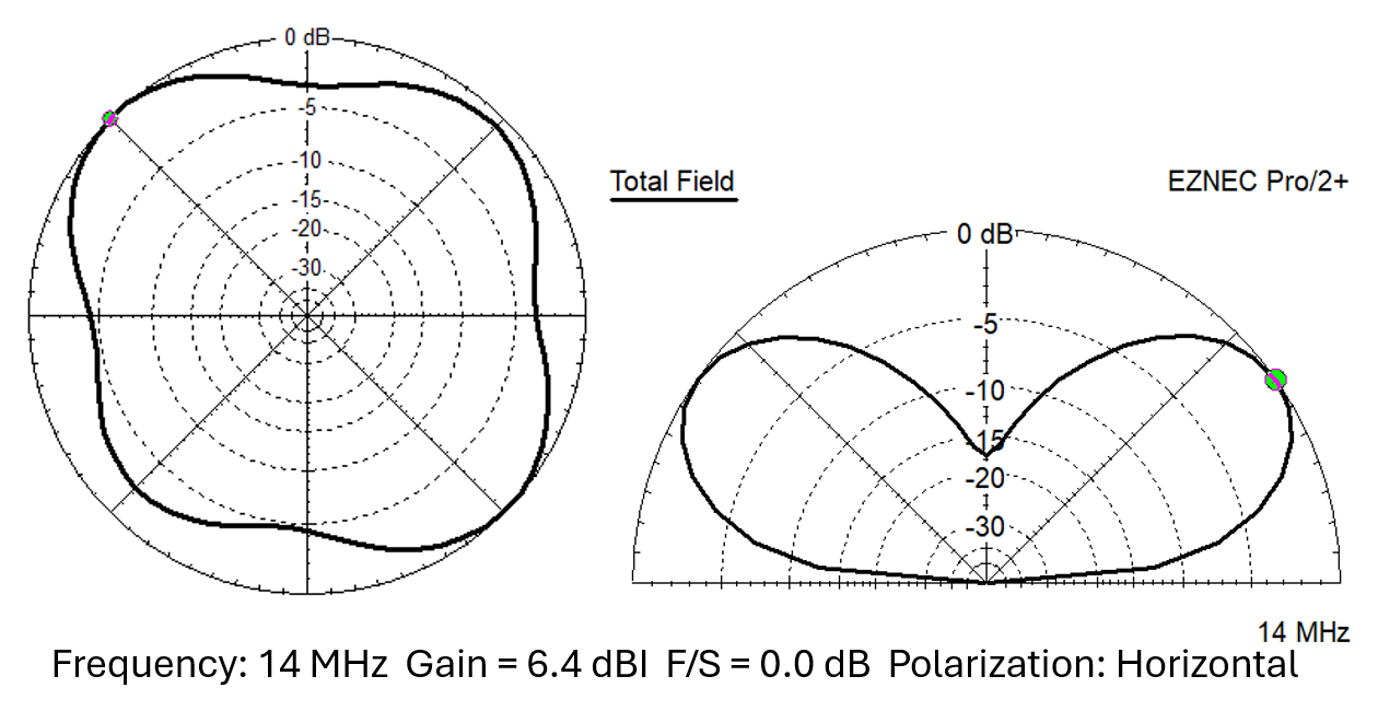
This record restores the product-specific 20 m evidence from the supplied seven-band EZNEC set. The two-dimensional image is the supplied azimuth-and-elevation plot. The interactive volume is a normalized reconstruction constrained by those two supplied cuts; it is not an independent native rerun.
Controlled source record
The supplied evidence identifies a nominal 141 ft horizontal loop at 30 ft over the EZNEC “Real Ground” selection and reports 6.4 dBi maximum modeled gain at 14 MHz. Model-relative +X follows the supplied azimuth plot's zero-degree reference, +Y is perpendicular in the horizontal plane, and +Z is up. The absolute compass bearing, numerical ground constants, original wire coordinates, segmentation, source definition, transformer loss, feed-line representation, and conductor-loss controls were not supplied.

Drag to rotate · scroll or pinch to zoom
Loading interactive pattern…
The supplied 20 m model shows broad rounded-square azimuth behavior with medium-angle elevation lobes and reduced zenith response. Because only two cuts and not the original model were supplied, use the reconstructed volume to understand those disclosed tendencies—not to infer unshown angular detail or compare absolute gain against a native case.
Source record: CHA-SKYLOOP-40-SUPPLIED-CUTS-30FT-20260815-R001-20M
A native MPAS 2.0 configuration using the HYBRID-MINI feed assembly, CHA MIL EXT 2.0, CHA MIL WHIP 2.0 radiator component, and one 25 ft ground radial.
Controlled setup record
The governed feed point and integrated RFI choke are at the base of CHA MIL EXT 2.0 on the CHA HYBRID-MINI. Four nominal 28 in extension sections contribute 106 in of deployed conductor; the equal 2 in overlap at each extension joint is derived from the published 218 in combined height. The 112 in CHA MIL WHIP 2.0 radiator component and its disclosed taper continue above the extension on +Z. One 25 ft ground radial extends from the feed point along model-relative −Y, with +X perpendicular in the ground plane.


Drag to rotate · scroll or pinch to zoom
Loading interactive pattern…
This is a complete CHA MPAS 2.0 configuration. CHA MIL WHIP 2.0 and CHA MIL EXT 2.0 are radiator components—not independent antennas. The radial and elevated-counterpoise returns are independently modeled; neither result qualifies an unspecified vehicle installation.
Model: CHA-MIL-EXT-WHIP-RADIAL25-20260815-R003-40M-PRIMARY
The dedicated CHA NVIS product geometry replaces the older MPAS horizontal-wire preview; no neighboring antenna is substituted as product evidence.
Controlled setup record
One pair uses two 38 ft radiator legs and the perpendicular pair uses two 25 ft legs. Four paracord runs continue to stakes 45 ft from the center, producing the documented approximately 85 ft footprint. The model boundary is the ideal 9:1 antenna terminal; transformer and coax loss are excluded.


Drag to rotate · scroll or pinch to zoom
Loading interactive pattern…
The high-angle tendency supports regional-path planning, but it does not promise coverage. Frequency, ionosphere, ground, noise, installed loss, and both stations still determine the usable link.
Model: CHA-NVIS-CROSSED-15FT-20260815-R003-40M-PRIMARY
A native product-specific case for the documented inverted delta loop—not a pattern borrowed from another loop or dipole.
Controlled setup record
The feed point is 6 in above average ground at model-relative X=0, Y=0. Two equal sloping conductor legs rise toward −X and +X to 11.84 ft, and the top conductor closes the 25.33 ft span between them. The entire loop lies in the X–Z plane; +Y is perpendicular to the loop and +Z is up. The antenna-terminal model excludes the matching-network loss, coax current, supports, and nearby conductors.


Drag to rotate · scroll or pinch to zoom
Loading interactive pattern…
Broadside and reduced-response directions follow the stated loop plane. Rotating the physical deployment rotates those directions. The accepted shape is simulated and uncorrelated; it does not include matching-network or feed-line loss.
Model: CHA-TDL-INVERTED-DELTA-TERMINAL-20260808-R001-20M-PRIMARY
A native MPAS Lite vertical case with the radiator and RF return explicitly assigned to signed model axes.
Controlled setup record
The antenna-terminal feed point is 6 in above average ground. The fully extended SS17 radiator rises 17 ft on model-relative +Z. One 25 ft counterpoise leaves the feed point on −X and terminates approximately 0.8 in above ground; +Y is perpendicular in the ground plane. HYBRID, coax, choke, common-mode current, supports, and nearby conductors are excluded.


Drag to rotate · scroll or pinch to zoom
Loading interactive pattern…
The asymmetric return is part of the modeled antenna, so its −X direction must be preserved in the deployment record. A different counterpoise, vehicle body, radial kit, or mount is a different installed system.
Model: MPAS-LITE-VERTICAL-20260808-R003-20M
A native LEFS 8010 case using both supplied wire sections as one 130 ft radiator. This is the featured military reference because the complete combined-wire configuration provides the documented 80 m path.
Controlled setup record
The antenna-terminal source begins at X=0, Y=0, Z=15 ft. The full 130 ft conductor—including the modeled six-turn loading coil beginning approximately 69 in from the terminal—continues horizontally in the model-relative +X direction at 15 ft. +Y is perpendicular to the wire and +Z is up. The 49:1 transformer, feed line, choke, supports, nearby conductors, and all losses are excluded.


Drag to rotate · scroll or pinch to zoom
Loading interactive pattern…
The 130 ft combined-wire installation is the relevant 80 m configuration. Its wire follows +X in this model; rotating the installed wire rotates the azimuth reference. The high-angle tendency supports NVIS planning, but the result remains uncorrelated simulation with approximate modeled coil geometry—not calibrated realized gain.
Model: CHA-LEFS-8010-EXTENDED-HORIZONTAL-20260809-R003-80M-PRIMARY
A native LEFS 8010 case using the 63 ft standard radiator and the approximate modeled physical loading-coil geometry.
Controlled setup record
The antenna-terminal source begins at X=0, Y=0, Z=15 ft. The 63 ft conductor—including the modeled six-turn loading coil approximately 69 in from the terminal—continues horizontally in the model-relative +X direction at 15 ft. +Y is perpendicular to the wire and +Z is up. The 49:1 transformer, feed line, choke, supports, nearby conductors, and all losses are excluded.


Drag to rotate · scroll or pinch to zoom
Loading interactive pattern…
The wire direction is +X in this model; rotating the installation rotates its real-world azimuth reference. The high-angle tendency supports NVIS planning, but this remains uncorrelated simulation with approximate modeled coil geometry—not calibrated realized gain.
Model: CHA-LEFS-8010-STANDARD-HORIZONTAL-20260809-R003-40M-PRIMARY
A native product-specific case for the full-size CHA SKYLOOP 2.0. It is not the compact CHA SKYLOOP 40 and does not inherit that product's source model.
Controlled setup record
The 286 ft closed radiator is modeled as a horizontal near-square loop 35 ft above average ground. X and Y define the two loop-side references; +Z is vertical. Feed system, feed-line current, conductor and transformer loss, support movement, terrain, and nearby structures remain outside the normalized pattern result.


Drag to rotate · scroll or pinch to zoom
Loading interactive pattern…
Upper-band lobes and reduced-response sectors must be oriented deliberately. This normalized model supports site planning; it does not establish installed gain, efficiency, bandwidth, or a guaranteed path.
Model: CHA-SKYLOOP-2-HORIZONTAL-35FT-20260808-R001-20M-PRIMARY
A dedicated native case for the complete CHA TD 2.0 using its two 60 ft radiator wires, termination, transformer boundary, and inverted-V geometry.
Controlled setup record
The two radiator arms descend in opposite signed X directions from the center support. +Y is perpendicular to the wire span and +Z is up. The accepted pattern is antenna-terminal simulation; transformer, termination, feed-line, choke, conductor, joint, support, soil, and site losses are not calibrated field measurements.


Drag to rotate · scroll or pinch to zoom
Loading interactive pattern…
This is one controlled TD 2.0 geometry. Selecting another documented wire length, termination arrangement, height, or orientation selects a different pattern record.
Model: CHA-TD2-TERMINATED-IV-60-20260815-R003-40M-PRIMARY
A native HPD-expanded TD 2.0 case using both 108 ft radiator wires. CHA HPD remains an expansion set, not a stand-alone feed system.
Controlled setup record
The two documented 108 ft radiator arms form the modeled 90-degree sloping-V. The signed X–Y references preserve its azimuth orientation and +Z is up. Transformer, termination, feed-line, choke, conductor, support, soil, and installed losses remain excluded from this normalized shape.


Drag to rotate · scroll or pinch to zoom
Loading interactive pattern…
The HPD wires expand the available TD 2.0 geometries; they do not by themselves guarantee the published average improvement in an uncontrolled field installation.
Model: CHA-HPD-TERMINATED-SV90-108-20260815-R003-40M-PRIMARY
A native CHA EMCOMM III BASE half-square case selected from the accepted product-wide configuration family.
Controlled setup record
The half-square rises and extends in the model-relative X–Z plane; +Z is up. Its 52 ft counterpoise leaves the feed point on −Y, while +Y is the opposite perpendicular reference. Rotating the installation rotates every stated axis. Transformer, feed line, supports, conductor loss, terrain, and nearby structures remain outside the normalized result.


Drag to rotate · scroll or pinch to zoom
Loading interactive pattern…
This directional half-square behavior belongs to the stated geometry. Other EMCOMM III BASE configurations have their own pattern records and must not inherit this orientation.
Model: CHA-EMCOMM-III-BASE-HALF-SQUARE-20260808-R001-40M-PRIMARY
A native horizontal-NVIS case for the CHA EMCOMM III PORTABLE complete wire system—not a BASE or neighboring end-fed-wire substitute.
Controlled setup record
The 73 ft horizontal radiator begins at the feed point and extends on model-relative +X. Its 25 ft counterpoise leaves the same feed point on −Y; +Y is the opposite perpendicular reference and +Z is vertical. Transformer, coax, choke, common-mode current, support, soil, conductor, and site losses remain excluded.


Drag to rotate · scroll or pinch to zoom
Loading interactive pattern…
The high-angle tendency supports regional-path planning only. It does not guarantee NVIS propagation, coverage, link margin, or receiving-unit suitability.
Model: CHA-EMCOMM-III-PORTABLE-HORIZONTAL-NVIS-20260808-R001-40M-PRIMARY
CHA PORTA-MAST is a support subsystem, so its radiation evidence must name the attached antenna. This accepted case uses a CHA B3D 120 ft inverted-V with a 20 ft center support.
Controlled setup record
The two wire arms descend in opposite signed X directions from the 20 ft center support; +Y is perpendicular to the wire span and +Z is up. Changing the attached antenna, center height, endpoint positions, mount, vehicle proximity, or wire bearing creates a different installed case.


Drag to rotate · scroll or pinch to zoom
Loading interactive pattern…
This is evidence for the complete named B3D/PORTA-MAST installation, not a universal “PORTA-MAST pattern.” A vehicle-supported mount also requires the nearby vehicle and exact mount position in its field record.
Model: CHA-B3D120-IV-20FT-PORTAMAST-20260815-R003-40M-PRIMARY
Ownership and field sustainment
A useful field system needs controlled documentation, realistic availability, replaceable components and a clear technical-support path—not merely an antenna in a shipping box.
Record the exact kit, accessories, radio chain, field geometry, support, feed line and RF return so another operator can rebuild the same approved setup.
Stock, quantity, custom-build requirements, export review, carrier conditions and receiving instructions can change the commitment. Confirm the current position before placing an order.
When a supported component is damaged or lost, individual replacement parts may be available without replacing an otherwise serviceable antenna system.
Equipment already in use belongs in the Chameleon Support Desk, where the installed configuration, photographs, measurements and troubleshooting history can remain together.
Whole-life decision rule: compare the exact delivered configuration, documentation, spares path, operator burden, confirmed lead time and replacement policy—not merely a headline antenna price.
Two practical purchasing paths
Chameleon does not hold a CAGE code or a direct federal contract vehicle. That does not prevent an authorized direct commercial purchase of stocked standard products.
For an authorized unit purchase card or another approved direct-payment method, contact Military Systems & Technical Support to confirm the complete configuration, availability, quantity, and shipping commitment before ordering.
Discuss a direct commercial purchaseIf the requirement needs a federal contract vehicle, formal integration, or contract-specific fulfillment, Chameleon will coordinate the opportunity with an established government procurement partner.
Request a procurement-partner handoffPurchasing authority, contract eligibility, export review, receiving-unit approval, and final configuration acceptance remain the customer’s responsibility.
Military equipment selection and purchasing
Military Systems & Technical Support helps customers identify the antenna family and complete field configuration that fit the real constraint. Share only unclassified information: the broad communications role, radio model, frequency family, power, mobility, support availability, setup objective, weight limit, quantity, and purchasing route.
Do not email classified information, CUI, exact operational locations, call signs, operational frequencies, deployment dates, or other mission-sensitive details.
Military Systems & Technical Support
Don Sherman — Military Antenna AdvisorDon@chameleonantenna.com775-344-9900Need help with equipment already in use? Open a private, guided technical case in the Chameleon Support Desk.
Open Chameleon Support Desk →
